AutomaticTransfer Switch Wiring
Transfer Switch Wiring: How to Wire a Transfer Switch
Transfer switches are basically used for switching power from a primary power source to a secondary or tertiary power source. They are useful for emergency power generators, in order to back up power from the utility source. A transfer switch may be a manual switch, automatic switch, or a combination of both. It becomes necessary to transfer power from a primary source to secondary source in case the incoming power quality deviates from set limits. A transfer switch is made up of an actuator and a toggle mechanism. An actuator can be activated either manually or automatically, in order to supply energy to the movable contacts on the toggle mechanism. Transfer switches prevent the damage of utility equipments by allowing for operation of the generator without back-feeding to the utility.
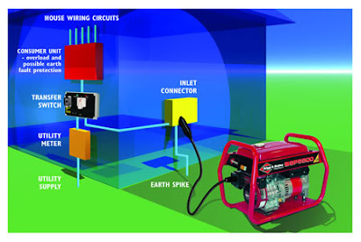
The automatic transfer switches are controlled with the help of a programmable logic controller (PLC), a relay logic, or an embedded controller. These circuits monitor the public utility power source constantly for any kind of fault condition. Once they find a fault with the utility power, the embedded controller automatically switches to the secondary source of power. Transfer switch wiring is important for a household generator. For the purpose, it is necessary to connect the properly sized wires to the three position switch. Following are the steps on how to wire a transfer switch.
As a basic security measure, it is important to turn off the power before attempting any type of main electrical power wiring. On taking a closer look at the transfer switch, one can observe six termination points on the transfer switch, along with three grounding screw terminals and three neutral terminals. The grounding screw terminals are connected directly to the frame of the switch, whereas the connection of rest of the termination and neutral points is made according to the next few steps.
Remove a small part of insulation from the wires which come from the generator itself, the power utility meter and the circuit breaker box. There should be four wires from each component. Out of these four wires from every set, one is used as the earth ground, one as neutral wire and the remaining two as power wires.
Connect all three of the grounding wires, each coming from a set, to the grounding bar mounted to the rear of the transfer switch. Connect the neutral wires to the ground connection bar which may also be tied to the rear of the transfer switch.
Next step involves the connection of the remaining two power wires from each set, to the two center lugs on the transfer switch. These lugs are connected to two large knife blade connectors. Attach the wires coming from the power utility meter to the two lower set of lugs on the transfer switch. The two wires from the generator should be connected to the two top lugs on the transfer switch, thus completing the wiring part.
All transfer switches do not have a remote start / stop contact block. However, if it's there, make a connection between the start / run wires from the generator and the auxiliary screw terminal mounted on the side of the transfer switch.
Automatic transfer switches monitor the incoming utility power for anomalies, like, brownouts, spikes or surges. If no anomalies occur for a set time, the transfer switch transfers back to utility power and commands the generator to turn off. The steps mentioned above can help a person to safely make proper connections of a transfer switch wiring.


