Transfer Switches Simplified
Practical tips for understanding and installing these devices in residential applications
Switch basics
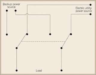
In its most basic form, a transfer switch for a 120/240V single-phase service is simply a double-pole, double-throw switch of proper ampere rating with a middle off position (Fig. 1). By design, it is a physical impossibility for both power sources to supply the load simultaneously, unless, of course, that is the intent. It's also impossible for the two sources to mix — or for one source to back feed into the other.
Installing a transfer switch is a relatively straightforward task. You install the switch upstream of the service entrance panel, which typically contains the main disconnect. You should locate it next to the entrance panel. For a retrofit, if the main disconnect is part of the service entrance panel, it's necessary for you to pull the meter (with electric utility permission) in order to de-energize the service entrance conductors. Then, reroute them into the transfer switch, wire in the generator, and refeed the service entrance panel. In all cases, you should use cable or raceway suitable for the environment and of proper ampacity. Make sure the neutral is run through unswitched, and the transfer switch enclosure is properly grounded. Where aluminum conductors are used, be sure to wire-brush the metal, apply corrosion inhibitor, and torque the lugs to the proper value.
For the electrician who has never retrofitted a transfer switch, the job is relatively straightforward, because it closely resembles the work involved with an ordinary service installation.
Manual versus automatic
A manual transfer switch must be actuated by the homeowner. After having ascertained that the electric utility outage is more than a momentary loss of power, the homeowner must manually start the engine, allow it to come up to speed and stabilize, and then throw the lever on the transfer switch into the generator position.
On the other hand, an automatic transfer switch (ATS) continuously monitors electric utility power. Fluctuations or serious power quality issues, which might precede an outage, trigger a start command to the generator. After backup voltage and frequency stabilize, the transfer switch brings the generator online. Once electric utility power is restored, with no fluctuations for a predetermined amount of time, the switch goes back to its normal position. After a cooling down interval, the generator is automatically shut down. All of these actions take place with no human intervention.
No matter which type of switch is being used, the foregoing discussion is based on the assumption that the generator is capable of supplying the total connected load, which is often not the case. Unless the residential load is unusually small or the generator is unusually large, successful operation depends on several factors.
With a manual transfer switch in place, the homeowner would first have to make his way to the service entrance panel. Many times, this would be done in the dark with a flashlight in hand. Prior to switching over to standby power, the homeowner would have to shut off individual breakers for nonessential branch circuits so as to shed part of the load and size it down to match the capability of the standby power plant. If the loads on their branch circuits weren't properly noted prior to this activity, it's easy to overload the capability of the generator right from the start.
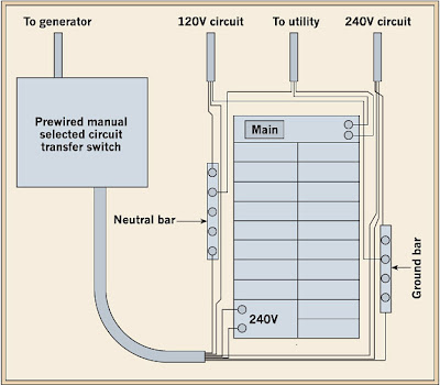
Fortunately, this process is not necessary with newer transfer switches. Several manufacturers provide selective load transfer switches (see Fig.2), which provide alternate power to only those branch circuits chosen in advance by the homeowner. Because this type of transfer switch carries only a small portion of the total load, it is smaller and moderately priced. A typical 6-circuit model, suitable for a 5,000W generator, sells for about $350.
Moreover, the electrician that performs the initial installation does not have to cut incoming power and perform heavy service entrance conductor work during the install. As the installer, all you have to supply is a 60A double-pole breaker to match the service entrance panel make and model.


