Reliance Controls Transfer Switch: Installation and Operating Instructions – Part II
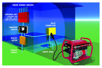
In the last issue we have talked in
details about the Reliance Controls transfer switch and its importance in power
backup system (Part I). In this part we
will discuss the installation and operating instructions of Reliance Controls
Transfer Kit Model 3006 HDK in details using illustrated figures and videos.
INSTALLATION
INSTRUCTIONS
A. Mounting
the Transfer Switch
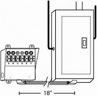
1. Position the transfer switch so that its bottom center is about 18 inches from the
bottom center of your load center. The end of the flexible conduit whip should be
lined up with a 3/4" knockout hole on the bottom of your load center (Figure 1).
Figure 1
2. Mark the position of the holes on the four
external feet with a pencil.
3. Anchor the transfer switch to the wall
with four appropriate anchors (with a flange of at least 3/8").
NOTE: Do not attempt to
bend the flexible conduit whip beyond its structural capabilities.
B. Connecting
the Flexible Conduit Whip to Your Load Center
1. Set up battery-powered lighting to clearly
illuminate
your work area.
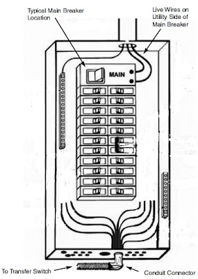
2. Turn off the main utility breaker (Figure 2).
Figure 2
3. Remove the cover of your load center. Keep
in mind that the
wires on the utility side of the main
breaker are still live and if
contacted could cause serious injury or
death. If available,
use a non-contact voltage detector to
insure that the power is
off on the non-utility side of the main
breaker.
4. Remove the appropriate knockout hole in
the bottom of your
load center with a screwdriver and hammer.
(See step A-1
above.)
5. Insert all of the wires extending from the
end of the flexible
conduit whip through the knockout hole.
Snap the conduit
connector attached to the whip into the
knockout hole.
C. Connecting
the Neutral and Ground Wire
1. Find the white wire (Neutral) and the
green wire (ground) among the wires from the transfer switch that you have inserted into the load
center.
2. Strip approximately 5/8” from the end of the white wire. Locate the neutral bar
and partially unscrew a terminal screw on the bar. Insert the stripped end
of the wire into the side of the bar under the screw and retighten the screw. (Figure 3)
3. Locate the ground bar. (It should be labeled.) Connect the green wire to the
ground bar in the same way as in step #2. In service entrance load centers, the
ground bar and neutral bar are frequently the same; if so, the ground and neutral wires can be
connected to either.
Figure 3
D. Installing
120 Volt Circuits
This section provides instructions for connecting the wires from your transfer
switch to the circuit breakers in your load center which control your appliances.
You should refer to the load planning you did previously to insure that side #1
and side #2 of the transfer switch are balanced. Wire the circuits, starting with
toggle Switch A. If a selected circuit is part of a multi-wire branch circuit, insure
the other branch circuit
that shares the neutral is also connected to the transfer switch. The
two circuits must be connected to opposing legs (phases) of the generator power and a
handle tie must be installed on the switch handles so that both legs are
transferred at the same time.
If you will not be installing any 240 Volt or multi-wire circuits, remove the
factory-installed handle tie(s) on the unit by loosening the setscrews on the tie. Let's assume that,
according to your load balancing plan, you will use Switch A to supply power to the
refrigerator. (Figure 4)
Figure 4
1.Turn off the refrigerator circuit breaker.
Disconnect the wire that is attached to the circuit breaker.
2. Find the black and red wires from the
transfer switch marked A.
3. Cut the red wire at a length convenient
for it to reach to the
refrigerator circuit breaker. Strip 5/8”
from the end of the
wire. Connect the red wire to the
refrigerator circuit breaker
and retighten the screw on the breaker.
4. Cut the black wire from the transfer
switch to a length convenient for attaching it to the wire you removed from the refrigerator circuit
breaker in #1. Strip 5/8” from the end of the wire.
5. Insert both wires—the one removed from the
refrigerator circuit breaker and the black wire for Switch A—into a yellow wire connecter.
Tighten the connection and push the connected wires back into the wiring
compartment of the load center.
This completes the connection of Switch A for your refrigerator. Label Switch A as
“REFRIGERATOR” on the identification pad on top of the transfer switch.
6. Repeat Steps 1 through 5 for each of the
remaining switches on your transfer switch according to your load balancing plan, taking into account
the following:
• See the next section for installing 240-Volt Circuits
• Remember to “Balance the Load”, dividing appliances with higher wattages
between the left and right side of the transfer switch
E. Installing
240 Volt Circuits
Reliance Controls 6-Circuit Transfer switch (In Kit) is shipped from the factory with one
installed handle tie on two adjacent circuits.
Let’s assume that, according to your set-up plan, Switches C & D on the 6-Circuit
transfer switch will be used to supply power to your well pump, a 240 Volt
appliance. (Figure 5)
1. Find the two red and the two black wires
marked C & D.
Figure 5
3. Disconnect the two installed wires on the
double pole breaker.
4. Cut the two red wires from Switches C
& D at a length convenient for them to reach to the double pole breaker. Strip 5/8” from the end of
each red wire. Connect both red wires to the double pole circuit breaker in place
of the wires you just removed from that breaker. It doesn’t matter in what order.
5. Cut the black wires marked C & D to a
length convenient to reach to the wires you removed from the double pole breaker in #3. Strip 5/8” from
the end of each wire.
6. Connect one of the wires you removed from
the double pole breaker in #3 with one of the black wires (either C or D) with a yellow wire connector.
Similarly, connect the other wire you removed with the remaining black wire with
a wire connector.
F.Completing
the Installation of the Transfer Switch
When you have wired all of the circuits from the transfer switch into your load center and
have properly installed the green and white wires to ground the unit, you have
finished the installation. (Figure 6) Just a few more steps to wrap things up.
Figure 6
1. Replace the cover of the load center.
2. If you have not already done so, fill in
the chart on the top of the transfer switch to identify your emergency
circuits and the toggle switches they correspond to.
3. Do not turn the main and individual
circuit breakers in your load
center back on until you have installed
all other transfer switch
components in Sections G, H and I which
follow.
G. Installing
and Wiring the Outdoor Power Inlet Box (included in kit)
Since you will be operating your generator outdoors in a location remote from your
electrical load center, it is recommended that you install an outdoor
power inlet box on an exterior wall of your house.
Because it is hardwired directly to your transfer switch, the power inlet box gives you
the flexibility to locate your generator just about anywhere outside away from a door or a window.
Reliance Controls Power Inlet Boxes are UL listed and can be used with the following
generator and building wire sizes:
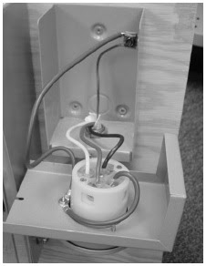
To install a Reliance Power Inlet Box (Figure 7):
1. Loosen the screw at the bottom front of
the box and lift off the cover.
2. Choose which knockout hole on the box is
most convenient to where you will be running the building wire into your house. Remove the knockout
with a screwdriver and hammer.
Figure 7
3. Plan to run enough building wire (check
electrical codes for the need for conduit) to reach your transfer switch, allowing extra length for ease of
wiring at the transfer switch end.
4. Using approved wiring methods, place a
cable or conduit connector (check codes) in the inlet box knockout hole and run enough building wire
into the box to allow easy wiring. Tighten the connector.
5. Mount the back plate of the power inlet
box where it will be convenient. Use the three holes in the plate.
6. Strip 5/8” from each building wire lead.
Loosen the green grounding screw on the inside of the box and insert the stripped end of the building
wire ground under one side of the grounding screw and retighten.
7. On the bottom of the inlet plug, insert
the white wire into the hole marked “W” and tighten the screw on the side of the plug. Do the same with the
red wire into the hole marked “X” and the black wire into the hole marked “Y”.
8. Replace the cover of the power inlet box
and tighten the screw.
H.Wiring
the Power Inlet Box to the Transfer Switch
All Reliance Controls transfer switches are designed to allow hardwiring between the
outdoor power inlet box and the transfer switch’s internal wiring compartment. This
installation is the most efficient, eliminates the need for longer generator power cords running through your
home to your transfer switch and eliminates the need for an additional junction box. To hardwire your
transfer switch to the building wire from the power inlet box (Figure 8A and 8B):
Figure 8A Figure 8B
1. Remove the front bottom wiring compartment
cover plate of the transfer switch by unscrewing the two screws securing the plate and then pulling out
on the bottom of the plate. Once the plate is removed, the wire leads necessary to
connect the incoming building wire can be easily accessed.
2. Punch out the knockout hole on the side of
the transfer switch wiring compartment.
3. Using approved wiring methods, place a
cable or conduit connector (check electrical codes) in the knockout hole, and pull enough building wire
into the inside of the wiring compartment to provide sufficient working length.
Tighten the connector.
4. Connecting the Wattmeters: Thread the black
building wire through the transformer ring attached to the left wattmeter before connecting it
to the black transfer switch wire. Likewise thread the red building wire through the
transformer ring attached to the right wattmeter before connecting it to the red transfer switch wire.
Connect the green to green and white to white wires with a red connector. Do not
thread these wires through the transformer rings (Figure 8B).
5. Complete the wiring by pushing the wires
back into the unit, putting the wiring compartment cover back in place and replacing the screws
that hold the cover plate.
I.Installing an Optional Power Inlet on your
Transfer Switch (not necessary in kit installation)
Although such an installation is not necessary with the Power Transfer Kit, your
Reliance Controls transfer switch is unique in that it allows the
installation of an accessory power inlet which allows you to plug your
generator directly into your transfer switch using a longer power cord. Use this option
only if the transfer switch is installed outdoors where it is sheltered from
the elements.
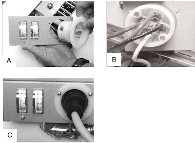
To install a power inlet on your transfer switch (Figures 9A-9C):
Figures 9
1. Purchase Reliance Flanged Power Inlet
model number L1420F for a 20 Amp inlet to accommodate 20 Amp power cords and small generators up to
5000 watts, or L1430F for a 30 Amp inlet to accommodate 30 Amp power cords and
generators up to 30 Amp. If you choose to,
you may also use the 30 Amp power Inlet from the Reliance PB30 Power
Inlet Box (supplied with the kit).
2. Remove the plastic Reliance logo panel
located on the right side of the wiring compartment cover to reveal the hole for the power inlet. One screw holds
this plate on the bottom.
3. Remove the entire wiring compartment plate
by removing the other bottom screw and pulling out on the bottom of the plate.
4. If your transfer switch has wattmeters,
make sure that the black wire from the transfer switch is threaded through the transformer ring connected to the
left wattmeter, and the red wire from the transfer switch is threaded through the
transformer ring connected to the right wattmeter.
5. Insert the power inlet into the hole in
the wiring compartment plate and fasten it with the two smaller screws included with the inlet. Do not refasten
the longer bottom screw at this time.
6. On the underside of the inlet, insert the
white wire into the hole marked “W” and tighten the screw on the side of the plug. Do the same with the red
wire into the hole marked “X”, the black wire into the hole marked “Y” and the
green wire into the hole marked “G”.
7. Replace the wiring compartment panel with
the two screws you removed in steps #2 and #3, inserting the longer screw through the bottom of the
flanged inlet plug.
J. Finishing
Up
According to your individual installation requirements, after you have completed all the steps necessary in
Sections G through I,
complete the system installation by doing
the following:
1. Turn on all of the circuit breakers in
your load center.
2. Turn on the main breaker.
3. Position all switches on the transfer
switch to the LINE position.
4. IMPORTANT! In order to insure that all wiring connections have been properly completed and that your
system functions
properly under generator power, it is
important to test each
circuit before turning on any devices or
appliances connected to
that circuit. Correct voltage output can
and should be checked
with a voltage meter at any convenient
electrical outlet on each
branch circuit that is wired through the
transfer switch. This
should be done under generator power with
the appropriate
circuit breaker switch in the “GEN”
position.
OPERATING
INSTRUCTIONS
You want your generator to be ready when you need it – so, it is important to perform the following steps once a month:
• Start and run generator power through your transfer switch circuits.
• Keep your fuel tank filled with fresh fuel.
With your Reliance Controls transfer switch installed, it is not
necessary
to turn off any of your load center
breakers when starting your generator, even when utility
power is fully functional. This is because the double throw
break-before-make action of the transfer switch prevents feeding generator power to the utility and,
conversely, prevents feeding utility power back to your
generator.
A. Transferring
from Utility Power to Generator Power in an Emergency
1. Make sure that all switches on the
Reliance Controls transfer switch
are in the LINE position.
2. Plug the male end of your power cord into
the generator. NOTE: If
your generator has only 20 Amp 125/250 V
output receptacles,
replace the 30 Amp male end of the power
cord with the 20 Amp
male plug end supplied in the kit. See
installation instructions with the 20
Amp plug.
3. Plug the female end of your power cord
into either the outdoor power
inlet box or directly into the transfer
switch, depending on how you
installed your system.
4. Start your generator outdoors and let it
warm to a point where it is
running evenly.
5. Turn the toggle switches on your Reliance
transfer switch to the GEN
position one at a time.
If you have a Reliance transfer switch with wattmeters, you can monitor the wattage load on your generator.
B. Transferring back to Utility Power When the Power Is Restored
1. Move all switches on the Reliance Controls
transfer switch back to
the LINE position.
2. Turn off your generator.
3. Unplug your power cord and store it.





Aditya Developers present City Apartments at NH-24, Ghaziabad. Aditya City Apartments offers 1bhk, 2bhk and 3bhk apartments on prime location. Booking @7676-222-888
ReplyDelete